Introduction
In the construction industry, construction plans are exchanged in various CAD files [DXF, DWG, STEP] apart from PDF formats.
The construction plan information, in any CAD file format, can be easily edited using supported tools or software. But PDF files are different and it poses challenges to edit. Hence, the shared PDF content is useful only for visibility. If the end user wants to do any operations like COGO [Expand COGO] or enhancements, they have to redraw the whole content again, which may lead to errors. In the construction industry, one error may lead to millions of losses. Hence, PDF to CAD file conversion is crucial.
PDF Forms:
- Vector PDF: PDF content is based on geometric values, and operations like zoom-in and zoom-out will be applied on entities depending on geometric value
- Raster PDF: PDF content is in image format with certain aspect ratio, and operations like zoom-in and zoom-out image will be blurred depending on aspect ratio
Conversion Process From PDF to DXF
How Does PDF to DXF Conversion Work?
A typical conversion involves understanding of the type of data found in the source and destination. Each PDF file captures a complete description of a document, including text, fonts, images and vector graphics. However, the PDF file format can only encode very simple graphic objects (entities). It can only store 2D text, lines and polygons and cannot store CAD arc or circle entities.
Factors To Consider In Conversion Process
In market, there are many PDF to DXF conversion tools. Some of the common issues faced by them are:
- Scaling
- Translations
- Orientation
- Content Styles [Fonts, Line Styles, Line Thickness and Color]
- Entity Splits
- Entity Wrong Merges
- Entity Type Mismatch
- Layer Mismatch
- Missing of Layers
Resolution Techniques
Following are some of the steps to be taken on the converted file data to get accurate results:
- Basic entity properties like line style, color and layer will be considered as the highest priority to adjust the entities
- Slope of the line
- Length of segments/line
- Entities start and end points
- Arc and circle sector and radius
- Searching for similar patterns, even rotated and scaled
Use Case Flows for Deviations
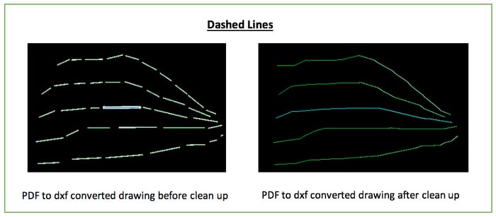
Dashed Lines Cases
- In an actual CAD file, if the line type is dashed /double dashed /dot-dashed, then after conversion of CAD to PDF to CAD, those lines will be split into multiple entities.
- These can be solved by slope and gap calculation along with thickness, color and layer.
- Sometimes solving these may lead to connecting wrong entities. To avoid such cases, give user the option to break anywhere or at an acceptable tolerance range of GAP and other parameters.
- This type of scenario can occur a lot with corner lines.
Sample Case of Dashed Lines
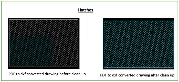
Hatches Case
- Most of the Hatches are filled types, but after converting back to CAD files, these Hatched entities will turn to polylines.
- These cases are difficult to identify directly. This can be done only with user input. User has to select one set of entities in the order they connect to become a hatch and defined algorithm will search for similar patterns, even scaled and rotated sets and makes them as the Hatches.
- These cases can observe most of the times in Boundaries.
Sample Case of Hatches
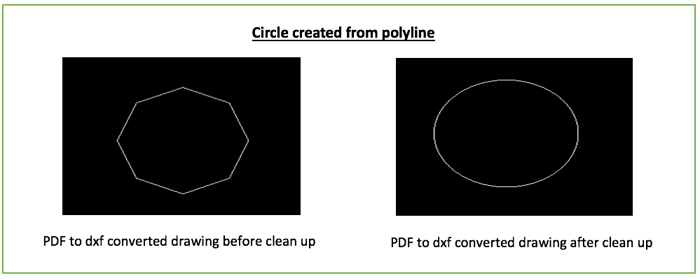
ARCs and Circles Case
- Most of the time after conversion, circles will become arcs
- This can be solved by checking the start and end points of arc. If they are near or within tolerance, then the arc can be converted into a circle with arcs radius.
- Sometimes circles will split into two arcs
- This can be solved by merging lines, but it needs to be checked if the arc sectors are matching or not.
- Sometimes circles will become multiple polylines
- This can be solved, if the polylines are closed and the length of each segment is within tolerance.
- Sometimes the polyline is not closed but the start and end points are same. In that case, it can be considered as a closed polyline.
Sample Case of Circles/Arcs
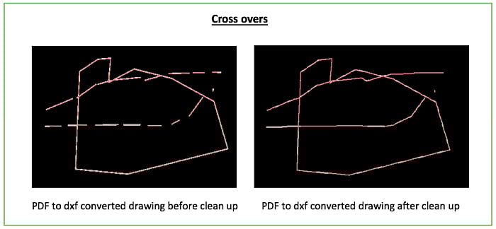
Crossovers
- Crossovers can be identified with line style and layer of the entities.
COGO
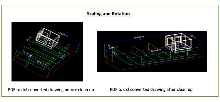
In construction industry, accurate Calculation of Area and Quantities (COGO) are more important than the appearance. After PDF to CAD conversion, we need to solve the following issues.
- Scaling: After PDF to CAD conversion, the drawing may be resized
- Translation: After PDF to CAD conversion, the drawing may be relocated to another origin coordinate
- Orientataion: After PDF to CAD conversion, the drawing may be rotated to certain angles
Solutions
For this, there are three solutions.
- Scale With Known Distance
To do this, user has to know two coordinates and distance between them. Based on the user input, we need to calculate the current distance of those coordinates and calculate the factor of actual distance (user input). The calculated factor needs to be same on all entities.
- Rotate With Known Bearing
To do this, user has to know two coordinates and bearing of those points. This is same as above and we need to calculate the current bearing of the coordinates and calculate the difference with actual bearing (user input). The calculated difference bearing will be applied on all entities.
- Transformation
To do this, user has to pair the coordinates with minimum of two pairs required to proceed. Based on the paired coordinates, we need to calculate the bearing, scale factor and translation and same will be applied on all entities.
Conclusion
The conversion poses problems to solve and each case might have a different solution. The suggestions on this page will help rectify and generalize some of the problems faced during conversion and get accurate results by defined algorithms and methodologies.
Getting an accurate design is a key factor for the construction industry. Each conversion ranging from PDF to CAD based documents, is of great importance and needs lot of experience to become proficient. Innominds has an expertise to build these kinds of tools that gives accurate results by using defined algorithms and calculations.
About Innominds
Innominds is a leading Digital Transformation and Product Engineering company headquartered in San Jose, CA. It specializes in ideating, designing, and developing cost-effective, cutting-edge digital product and application solutions and services for your business’ IT needs. Starting from inception of ideas, offering Product Lifecycle Management Services, Legacy Transformations, Cloud Engineering and Design Architecture among others, we have got it covered for you. We help companies in accelerating their Digital Transformation evolution. With over 12 years of experience in building digital products from scratch and over 100 products engineered, Innominds is well placed to cater to all your products and applications requirements.
Interested! For any demos or project discussions, please write to us at marketing@innominds.com and know more about our offerings.