Introduction
Have you ever imagined using an Android app to send data over UART, read data from an I2C device address or even to control motor orientations through PWM lines? Well, you might be imagining of GPIO and SPI. You are right, that’s possible, too. We will touch upon the basics of GPIO, UART, I2C, SPI, and PWM peripherals in the next section.
Peripheral SDKs opens a whole new realm of possibilities for application development that leverage the capabilities of underlying hardware in your system. It brings full stack development for an integrated feature of your choice.
What makes Peripheral SDKs so important and what is the challenge that makes it not so widespread? The challenge is to control these peripherals through Android OS and use them in developing solutions. The conventional way is to write low-level applications to control hardware specific components.
What Do You Need to Know to Build an Android Peripheral SDK?
Developers need to understand below mentioned topics before starting to build SDK.
- Android Application Development
- Android Frameworks
- JNI
- HAL
- Kernel (Device Driver Development)
- Peripherals (GPIO, UART, I2C, SPI, and PWM)
- Platform Board Configurations
What Do You Need to Have? (Tools & Environment)
- Your favourite IDE for android application development
- Linux system & environment to build platform
- Hardware and test setup
Before we get into the responsibilities of peripherals in terms of APIs, let’s get some of its basics, so that it becomes easier to align with the use cases you want to have.
GPIO
General Purpose Input Output (GPIO) is the most frequently used peripheral in embedded systems. These are the dedicated pins assigned on embedded boards. The developer must enable or disable GPIO pin, and set GPIO pin as input or output. This can be done through software configurations at board level or during runtime. Generally, GPIO pins are used to send triggers (high or low) when connected to some components or sub-systems on board. Any external hardware interrupts mapped to GPIO can be used to drive a software component.
Example: If the user inserts USB cable to the board, the interrupt generated drive the mapped GPIO pin to high (1) or low (0) (as per the design). This change in GPIO value will be detected by the device driver code, which will, in turn, set the desired course of action.
UART
Universal Asynchronous Receiver/Transmitter (UART) is a hardware device used for asynchronous serial communication. Their speed and data format are configurable. Generally, it is used for debugging embedded boards, but it isn’t only confined to it. These are also used for data transfer where lower communication speed is acceptable. The packet format contains start bit, data frame, a parity bit and a stop bit.
I2C
Inter-Integrated Circuit (I2C) is synchronous, multi-master and multi-slave bus. They are used in short distance intra-board communication. Sensors like temperature, pressure, accelerometer, and gyro use I2C protocol and are connected on I2C bus of the embedded board. The I2C configuration includes dedicated pins exposed for development. These I2C devices (sensors in this case) have device address (used for detecting the device) and set of data address, which holds data written by programmer or sensor values. In our case, an application developer can select the sensor from the list displayed on the screen (physically connected to the board) and read and write the data to it as per the intended use cases.
Example: App developer wants to display temperature value on the screen at an interval of every five minutes, so the developer can implement an algorithm to read a specific register or set of registers of the I2C device at the defined interval.
SPI
Serial Peripheral Interface (SPI) is a synchronous serial communication used for short distance communication. They have a speed that is faster than I2C. SPI devices have four physical connections, which denote SPI bus logic signals. They are Serial Clock (SCLK), Master Out Slave In (MOSI), Master In Slave Out (MISO) and Slave Select (SS). Many sensors, if not I2C, are based on SPI. This depends on a vendor’s choice for the sensor product. These devices have address using which, data can be accessed.
Example: App developer can read the value from a pressure sensor and generate an alarm if the value is crossing the threshold.
PWM
Pulse Width Modulation (PWM) is the signal (wave) generated on microcontrollers. They are governed by frequency and duty cycle (on and off period of the signal). They are used to control the motors (used in gimbles, robots, drones, etc). In our case, we have connected the APQ8053 processor to PIC microcontroller over SPI for sending commands related to PWM frequency and duty cycle. The microcontroller that is based on the frequency and duty cycle value generates PWM signal on the physical line where the motors are connected. This causes the motor to rotate at calculated speed and angle.
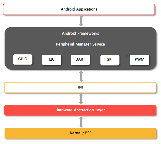
PeripheralManagerService
The above figure shows the design approach to implement peripheral SDK. At the core of Android or perhaps other OS’es, the application framework API’s interact with system services to access the underlying hardware. They manage almost everything in Android platform. The application framework gives developers enough flexibility to customize and develop applications. The services run in the background ensuring high responsiveness to the main thread i.e. UI thread of the application. The execution cycle of this service is managed by framework with start, bind and stop API calls.
Here, a systems service has an important role in exposing hardware’s functions to the application. The life of a system service is from boot to reboot (life of the system). There are many system services available in Android, but we will focus on “PeripheralManagerService” that we will be adding to system service.
The path framework/base/services/java/com/android/server contains java files for this service (like other). For most of the services, there is a JNI binding that interacts with lower layers like the kernel. As we know, this service will be started during the booting process (zygote starts system server, which in turn starts this service).
Later, we create I/O managers and interface them with PeripheralManagerService. The I/O managers are GPIO manager, I2C manager, PWM manager, UART manager, and SPI manager. These are the applications that hold the business logic you intend to have.
Responsibilities (APIs exposed for the developer)
Based on the requirements, the functional responsibilities of PeripheralManagerService can be defined. Here, in this case, the following are defined as the APIs.
- Get_GPIO_List:
This is to get the list of GPIO available for the application developer to work with - Get _I2C_BUSList:
To get the list of I2C buses available for the application developer on the given system - Get_PWMList:
To get the number of PWM lines available on the system - Get_SPI_BUSList:
To get the list of SPI buses available for application developer on the given system - Get_UARTList:
To get available UART ports for the application developer to read and write from - OpenGPIO
To open the requested GPIO pin file that enables the access to actual GPIO hardware - OpenI2CDevice:
Open I2C device for which, the address is provided by the developer - OpenPWM:
Open PWM control file, through which, the application developer can send control commands - OpenSPIDevice:
Open SPI device, for which the address is provided by the application developer - OpenUARTDevice:
Open UART port, as requested by the application developer
Similarly, the I/O Managers have their set of functional responsibilities that are defined below as APIs:
-
GPIO:
SetDirection : Sets GPIO directions (In or Out) SetValue : Sets the value (1 or 0) SetActiveType : Set the active level (Active low or high) SetEdgeTriggeredType : Set the trigger type to use for interrupt (None, Rising and Falling) GetValue : Get GPIO value GetName : Get GPIO name
The approach also has the provision to register for the call back that will be invoked on the activity happening on the GPIO pins. This gives application’s developer chance to develop applications based on interrupt-based systems.
-
I2C:
Read : Read data from an i2c device ReadRegBuff : Read multiple bytes from provided register address ReadRegByte : Read a byte from provided register address ReadRegWord : Read 2-byte word from provided register address Write : Write data to I2C device WriteRegBuff : Write multiple bytes to provided register address WriteRegByte : Write a byte to provided register address WriteRegWord : Write a 2-byte word to provide register address GetName : Get I2C device name -
PWM:
SetEnabled : Enable application provided PWM pin/line SetPWMDutyCycle : Set duty cycle for enabled PWM pin/line SetPWMFreqHz : Set frequency of the signal generated on selected PWM pin/line GetName : Get PWM device name -
SPI:
Read : Read byte data from the device SetBitJustification : Set ordering of bits in byte data SetBitsPerWord : Set number of bits/word SetCSChange : Set chip select SetDelay : Set delay between transfers Transfer : Transfer to and from SPI device Write : Write data to the device GetName : Get SPI device name -
UART:
Read : Read data from the device SendBreak : Set break interval time SetBaudRate : Set selected UART baud rate SetDataSize : Set selected UART data size SetHWFlowControl : Set hardware flow control mode SetModemControl : Set selected modem control line SetParity : Set parity mode of the selected UART SetStopBits : Set stop bit for selected UART SetWrite : Write data to the device
The approach also has the provision to register for the call back that will be invoked on the activity happening on the UART ports like incoming data.
Call Flow for GPIO
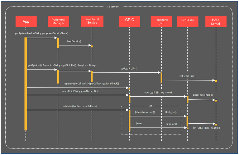
Figure 2 shows the execution call flow for a GPIO use case. To control the peripherals connected to the board, an application must get the handle to service from the peripheral manager and it must know the available list of GPIO’s pins. The application queries the list of GPIO’s from the peripheral service. This service interfaces with HAL to get the GPIO list. The application will get the list of GPIO names (pins are addressed using names). An application must register for call back function that will be invoked when any signal change happens in GPIO. In a Linux environment, these peripherals can be accessed using device files. An application can open a GPIO device file by passing the hardware pin name. Using the device handle, an application can set the direction and value for the GPIO.
In the use case shown above, the GPIO pin direction is set to OUT. So, when an application sets the value to ‘1 (enable)’ or ‘0 (disable)’, the end device connected to the GPIO pin is affected. Here, a simple LED is connected to this pin, which is turned on and off using the application.
The development work involves changes in following code paths:
- Application work in packages/apps/peripherals
- Service related changes in framework/base/core/java/android/ and framework/base/services/core/java/com/android/server
- Android native code changes in framework/base/services/core/jni
- Kernel interfacing in HAL layer - hardware/peripheral
In continuation of this development, the kernel driver should enable the user space access through device files, opening the channel for communication. Lastly, the platform directory structure should be known to make the relevant configurations to get the drivers exposed to the HAL layer. It will establish an end-to-end connection for the intended use case.
We have used QUALCOMM’s APQ8053 platform running Android N. Basically, this approach can be implemented on any platform. The operating system should give enough flexibility and maintainability to establish the working stack like Android.
Conclusion
In this blog, we have seen the possibility of controlling the peripherals using a HLOS that is targeted for mobile phone devices. This is achieved using the flexibility and development features offered by Android. It provides new opportunities for developers to use the underlying hardware functionality to develop IoT targeted applications. Applications can not only control sensors using I2C peripheral but also camera gimble and motors using PWM lines. SDK manager can be used to develop a full-fledged peripheral control feature or as an automated test suite to verify the functionality of peripheral features.
About Innominds
Innominds is a leading Digital Transformation and Product Engineering company headquartered in San Jose, CA. It offers co-creation services to enterprises for building solutions utilizing digital technologies focused on Devices, Apps, and Analytics. Innominds builds better outcomes securely for its clients through reliable advanced technologies like IoT, Blockchain, Big Data, Artificial Intelligence, DevOps and Enterprise Mobility among others.
From idea to commercialization, we strive to build convergent solutions that help our clients grow their business and realize their market vision.
Interested! For any demos or project discussions, please write to us at marketing@innominds.com and know more about our offerings.